Структура чип-резистора
Чип-резистор состоит из четырех частей: подложки, слоя резистивной пленки, электрода и защитной среды, а часть электрода разделена на внутренний электрод (серебро-палладий), переходный слой (никель), внешние электроды (в основном оловянные). -стронций).
Подложка чип-резистора представляет собой керамический материал из оксида алюминия высокой чистоты, который обладает исключительно высокой механической прочностью и прочностью изоляции, отличной теплопроводностью и устойчивостью к высоким температурам; слой резистивной пленки в основном представляет собой стеклянную глазурь на основе оксида рутения после высоких температур. Стрельба делает это; электрод внутреннего слоя обычно представляет собой шелкографию или погружение, а повторно спеченный серебряный слой, переходный слой и внешний электрод представляют собой генотипы из никеля и олова с гальваническим покрытием. Защитный слой представляет собой глазурь из спеченного стекла при необычно высокой температуре.

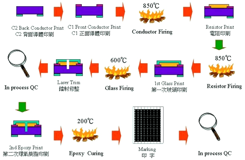
Процесс производства и процесс чип-резисторов
Печать на заднем электроде→ Обжиг→Печать поверхностного электрода→Обжиг→Печать резисторов→Обжиг→Печать на первичном стекле→Обжиг→Лазерная обрезка→Печать на вторичном стекле→ Печать меток→ Обжиг→Первичная резка→Заделка концов→ Обжиг→Вторичная резка → Электроды для гальваники → Тест Сортировка → Обмотка и упаковка

Проблемы применения чип-резисторов
Резисторы SMD, как правило, производятся с помощью автоматизации в больших масштабах, и консистенция продукта хорошая. Наиболее частых проблем в поступающих материалах не так много, а в процессе использования часто возникают следующие проблемы:
1 Электрод отваливается: если это происходит после сварки, причину следует проанализировать с двух точек зрения: во-первых, прочность сцепления электродов самого резистора плохая, а во-вторых, электрод сгорел из-за высокой температуры во время сварки, особенно во время сварки. ситуации ручной сварки. Эта ситуация подтверждается испытанием на термостойкость пайки (260℃*10S, проверка под микроскопом).
2 Разрушение подложки: эта ситуация в основном вызвана повреждением сопротивления внешним механическим воздействием. Конечно, термические напряжения также могут вызывать разрушение подложки, но на практике это случается редко.
3 Изменение значения сопротивления: как правило, значение сопротивления становится более заметным и дает сбой. Эта ситуация в основном вызвана длительной перегрузкой. Схемы, используемые в чип-резисторах, часто имеют относительно высокую плотность компонентов и плохие условия рассеивания тепла. Работая в таких суровых условиях в течение длительного времени, при выборе резисторов следует учитывать снижение мощности, чтобы продлить срок службы чип-резисторов.
4 Окисление внешнего электрода: эта ситуация повлияет на эффект сварки чип-резистора и легко приведет к ложной сварке. Окисляется ли внешний электрод, можно судить по двум аспектам. Один из них - наблюдать под микроскопом, и можно увидеть, что внешний электрод черный; второй – провести тест на паяемость (235°C*3 с), чтобы сохранить олово на внешнем электроде (требуется, чтобы площадь покрытия клеммы припоем превышала 90%).
Пример отказа резистора 1
Случай 1: Guangdong XXX Electronics Co., Ltd. Случай разрушения основной панели V9636
Time: July 10, 2020
Recently in the quality control report of the production line, R407/2.2Ω resistors break on the main panel of A V9636 were found with a defect rate of 0.5% (sometimes as high as 4%). The root cause of the badness here is:
1. The V-groove between the panels of the AV9636 main panel is relatively shallow, and it isn’t easy to separate the boards. The manufacturer used too much force during the board-splitting process, breaking the resistor body
2. For the defective products brought by the engineering personnel, the relevant personnel of Gaohua confirmed that some of the semi-finished PCB boards had not been tested
Our company’s solution to the above problems is as follows:
1) Relevant personnel must inform the PCB manufacturer to change the V-groove, and IQC is responsible for confirming the effect of the change.
2) Please ask the developer to change the PCB board (AV9636-0), R408 to 2.2Ω, and R407 to a copper skin for a direct short circuit.
3) For the semi-finished PCB boards in stock (AV9636-0), after communicating with the outsourced manufacturer, we agree to return the boards that arrived before July 10, 2020, to the factory without affecting the average production of our factory Retest.
4) The outsourced manufacturer will make the corresponding sub-board tooling for the produced PCB board during production, and the outsourced manufacturer will design the tooling;
5) Personnel testing must be arranged when our production line uses the boards that arrived before July 10, 2020.
Resistor Failure Case Study 2
Case 2: Zhejiang XXX Electronic Technology Co., Ltd. VD017K game has no function case
Time: July 5, 2018
the product line produced VD017 K, and about 70% of the games on the machine had no function (sometimes no function). After analysis and testing, it was found that the decoding board R17 (6.8 kΩ /1/16W) deteriorated, resulting in low voltage. This board is a new patch, batch numbers: 2629 and 2630. Now do the following:
1. For further analysis and verification, please use another manufacturer’s 6.8kΩ / 1/16W (material number: 0090002) chip resistor 300PCS.
2. Replace R17 directly when reproducing, measure the resistance value after completion, and ask QE to verify.
3. The supply department should notify the external manufacturer to assist in the investigation of the resistor supplier, suspend the use of resistors from this manufacturer, and at the same time invite the manufacturer to come to take samples and analyze them.
4. Please ask the Type Experiment Center to test and verify all the specifications of the manufacturer’s resistors and take samples of the wrong resistors for analysis.
5. Please ask the relevant department to check the inventory of the resistors of this manufacturer and check whether there are resistors of the exact specification from other manufacturers simultaneously. If not, please immediately ask the supply department to purchase a resistor of the precise specification from other manufacturers.
After re-examination, the main reason for the failure of chip resistors is caused by poor test fixtures. There is a row of thimbles on the decoder board test frame (this row of thimbles is on the game signal output socket of the decoder board), and there is a skew phenomenon. Resistor failed.

The Chip Resistors from Risunsemi
Risunsemi recommends high-quality chip resistors to you. Click the link below to search for the chip resistors you need!

