

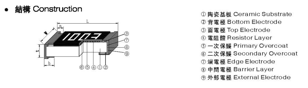
Estrutura do Resistor de Chip
O resistor de chip compreende quatro partes: o substrato, a camada de filme resistivo, o eletrodo e o meio protetor, e a parte do eletrodo é dividida em eletrodo interno (prata-paládio), camada de transição (níquel), eletrodos externos (principalmente estanho -estrôncio).
O substrato do resistor de chip é um material cerâmico de alumina de alta pureza, que possui resistência mecânica e resistência de isolamento excepcionalmente altas, excelente condutividade térmica e resistência a altas temperaturas; a camada de filme resistivo é principalmente pasta de vidro à base de óxido de rutênio após altas temperaturas. O disparo faz isso; o eletrodo da camada interna é geralmente serigrafado ou imerso, e a camada de prata ressinterizada, a camada de transição e o eletrodo externo são genotípicos de níquel e estanho galvanizados. A camada protetora é um esmalte de vidro sinterizado de temperatura incomum.
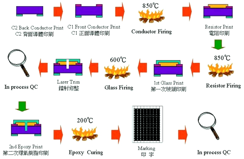
Processo de produção e processo de resistores de chip
Voltar Impressão de eletrodo→ Queima→Impressão de eletrodo de superfície→ Queima→ Impressão de resistor→ Queima→Impressão de vidro primário→ Queima→Recorte a laser→Impressão de vidro secundário→ Impressão de marca→ Queima→Corte primário→Vedação final→ Queima→Corte secundário → Eletrodos de galvanoplastia → Teste Classificando → Tapando e Embalando
Problemas na aplicação de resistores de chip
Os resistores SMD são geralmente produzidos por automação em grande escala e a consistência do produto é boa. Os problemas mais comuns na entrada de materiais não são muitos, e os seguintes problemas ocorrem frequentemente durante o uso:
1 Eletrodo cai: Se isso acontecer após a soldagem, o motivo deve ser analisado sob dois aspectos: primeiro, a força de adesão do eletrodo do próprio resistor não é boa e, segundo, o eletrodo é queimado devido à alta temperatura durante a soldagem, especialmente durante situações de soldagem manual. Esta situação é verificada pelo teste de resistência ao calor da solda (260℃*10S, verificado ao microscópio).
2 Fratura do substrato: Esta situação é causada principalmente pela resistência sendo danificada por estresse mecânico externo. Obviamente, o estresse térmico também pode causar fratura do substrato, mas é raro na prática.
3 Variação do valor da resistência: Geralmente, o valor da resistência fica mais proeminente e falha. Esta situação é causada principalmente por sobrecarga de longo prazo. Os circuitos usados em resistores de chip geralmente têm densidade de componentes relativamente alta e condições de dissipação de calor ruins. Trabalhando em condições tão adversas por um longo tempo, um projeto de redução de energia deve ser realizado ao selecionar resistores para prolongar a vida útil dos resistores de chip.
4 Oxidação do eletrodo externo: Esta situação afetará o efeito de soldagem do resistor de cavaco e facilmente causará solda falsa. Se o eletrodo externo está oxidado pode ser julgado a partir de dois aspectos. Uma é observar ao microscópio, e o eletrodo externo pode ser visto como preto; a outra é realizar um teste de soldabilidade (235°C*3s) para manter o estanho no eletrodo externo (requer que o terminal tenha uma área de cobertura de solda maior que 90%)
Estudo de caso de falha de resistor 1
Caso 1: Guangdong XXX Electronics Co., Ltd. Um caso de fratura por resistência do painel principal V9636
Time: July 10, 2020
Recently in the quality control report of the production line, R407/2.2Ω resistors break on the main panel of A V9636 were found with a defect rate of 0.5% (sometimes as high as 4%). The root cause of the badness here is:
1. The V-groove between the panels of the AV9636 main panel is relatively shallow, and it isn’t easy to separate the boards. The manufacturer used too much force during the board-splitting process, breaking the resistor body
2. For the defective products brought by the engineering personnel, the relevant personnel of Gaohua confirmed that some of the semi-finished PCB boards had not been tested
Our company’s solution to the above problems is as follows:
1) Relevant personnel must inform the PCB manufacturer to change the V-groove, and IQC is responsible for confirming the effect of the change.
2) Please ask the developer to change the PCB board (AV9636-0), R408 to 2.2Ω, and R407 to a copper skin for a direct short circuit.
3) For the semi-finished PCB boards in stock (AV9636-0), after communicating with the outsourced manufacturer, we agree to return the boards that arrived before July 10, 2020, to the factory without affecting the average production of our factory Retest.
4) The outsourced manufacturer will make the corresponding sub-board tooling for the produced PCB board during production, and the outsourced manufacturer will design the tooling;
5) Personnel testing must be arranged when our production line uses the boards that arrived before July 10, 2020.
Resistor Failure Case Study 2
Case 2: Zhejiang XXX Electronic Technology Co., Ltd. VD017K game has no function case
Time: July 5, 2018
the product line produced VD017 K, and about 70% of the games on the machine had no function (sometimes no function). After analysis and testing, it was found that the decoding board R17 (6.8 kΩ /1/16W) deteriorated, resulting in low voltage. This board is a new patch, batch numbers: 2629 and 2630. Now do the following:
1. For further analysis and verification, please use another manufacturer’s 6.8kΩ / 1/16W (material number: 0090002) chip resistor 300PCS.
2. Replace R17 directly when reproducing, measure the resistance value after completion, and ask QE to verify.
3. The supply department should notify the external manufacturer to assist in the investigation of the resistor supplier, suspend the use of resistors from this manufacturer, and at the same time invite the manufacturer to come to take samples and analyze them.
4. Please ask the Type Experiment Center to test and verify all the specifications of the manufacturer’s resistors and take samples of the wrong resistors for analysis.
5. Please ask the relevant department to check the inventory of the resistors of this manufacturer and check whether there are resistors of the exact specification from other manufacturers simultaneously. If not, please immediately ask the supply department to purchase a resistor of the precise specification from other manufacturers.
After re-examination, the main reason for the failure of chip resistors is caused by poor test fixtures. There is a row of thimbles on the decoder board test frame (this row of thimbles is on the game signal output socket of the decoder board), and there is a skew phenomenon. Resistor failed.

The Chip Resistors from Risunsemi
Risunsemi recommends high-quality chip resistors to you. Click the link below to search for the chip resistors you need!