
Resistor networks are components of various electrical and electronic circuits to control current flow. They typically create voltage dividers, impedance-matching, and attenuation networks. In this article, we will explore the definition, types, main application products, functions, equivalent circuits, and ratings of resistor networks.
Definition of Resistor Networks
A resistor network combines resistors connected in a specific pattern or configuration to achieve a particular electrical function. Resistor networks can comprise multiple resistors connected in series, parallel, or combination.
Types of Resistor Networks
There are several types of resistor networks, including:
1 Series Networks: In a series network, resistors are connected end-to-end in a single line. The current flows through each resistor in turn, with the total resistance of the network equal to the sum of the individual resistances.
2 Parallel Networks: In a parallel network, resistors are connected in multiple paths, each containing one or more resistors. The total resistance of the network is calculated using the formula for parallel resistance.
3 Combination Networks: Combination networks combine series and parallel networks to achieve a specific electrical function. They can be used to create complex impedance matching and attenuation networks.
Main Application Products
Resistor networks are used in a wide range of electronic applications, including:
Audio and video equipment: Resistor networks are used in audio and video equipment to control the volume and adjust the brightness and contrast of the display.
Power supplies: Resistor networks are used to control the voltage and current.
Communication systems: Resistor networks control the impedance and attenuate the signal.
Functions of Resistor Networks
The primary function of a resistor network is to control the current flow in a circuit. They are used to create voltage dividers, impedance matching networks, and attenuation networks and to maintain the voltage and current in power supplies.
Resistor network also has the characteristic of miniature, high-density assembly, stable electrical capability, high reliability, and combinations of different ohmic.
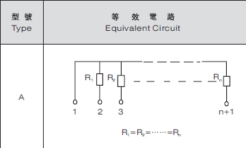
Equivalent Circuits
The equivalent circuit of a resistor network depends on the specific configuration of resistors used. For example, a series network can be represented by a single resistor with a value equal to the sum of the individual resistors. A parallel network can be represented by a single resistor that has a value equal to the reciprocal of the sum of the reciprocals of the individual resistors.
Ratings of Resistor Networks
The ratings of resistor networks depend on the specific application and the resistor configuration. The main ratings include the resistance value, power rating, tolerance, and temperature coefficient.
1 Resistance Value: The resistance value of a resistor network is the total resistance of all the resistors in the network. It is measured in ohms Ω and is typically specified as a range or a specific value.
2 Power Rating: The power rating of a resistor network is the maximum amount of power it can handle without overheating. It is measured in watts W and is typically specified as a range or a specific value.
3 Tolerance: The tolerance of a resistor network is the maximum allowable deviation from the specified resistance value. It is typically identified as a percentage of the nominal value.
4 Temperature Coefficient: The temperature coefficient of a resistor network is the rate at which its resistance changes with temperature. It is typically specified in parts per million per degree Celsius (ppm/°C).
In conclusion, let us understand the thick film network resistor ratings specifically.
Power Rating: 1/8W (1/4W)
Max. Working Voltage: 200V
Max. Overload Voltage: 280V
Jumper Rated Current: 2A
Resistance Temperature Coefficient: 10Ω<R<1MΩ: ±100ppm/℃, 1Ω<R<10Ω, 1MΩ<R<10MΩ: ±250ppm/℃
Resistance Tolerance: ±1%, ±2%, ±5%, Jumper: <50mΩ
Resistance Range: 0Ω(Jumper), 1.0Ω~10MΩ, E-24 series
Operating Temperature Range: -55~125℃
Rated Temperature: +70℃
How to Identify the Model of Resistor Networks
The model of a resistor network is typically indicated by a combination of letters and numbers that represent the resistance value, tolerance, and package type. Here are some steps to help identify the model of resistor networks:
1 Look for markings on the resistor network: Most resistor networks will have markings that indicate the model number and other important information. Look for letters and numbers that may be printed or stamped on the surface of the resistor network.
2 Check the datasheet: If the markings on the resistor network are not transparent or legible, you can check the datasheet for the component. The datasheet will typically provide the model number, resistance value, tolerance, and package type information.
3 Measure the resistance value: If you cannot find any markings or data sheets, you can measure the resistance value of the resistor network using a multimeter. Once you have the resistance value, you can compare it to typical values for resistor networks to help identify the model.
4 Compare the physical characteristics: Resistor networks come in different sizes and shapes, and some may have unique physical features that can help identify the model. Compare the resistor network’s size, shape, and pin configuration to images of resistor networks online or in catalogs to help narrow the options.
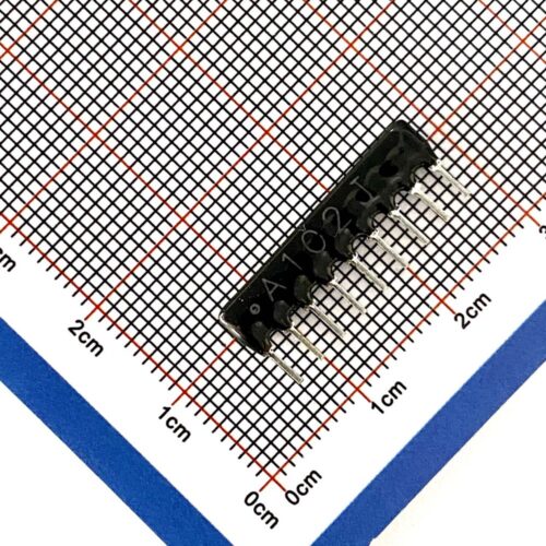
So, how to identify the model of the resistor network at work? First, let’s look at the following picture:
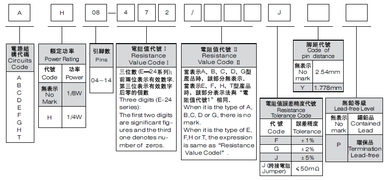
As shown in the figure above, the conventional resistor network model is: A07-472J; A refers to the A-type circuit structure, 07 refers to 7 pins, and J refers to ±5 % accuracy. About 472, we need to know that the resistance code of the resistor network follows the rules of the IEC E-24 series; the following is IEC E-24 Series Resistance Cross Reference List.
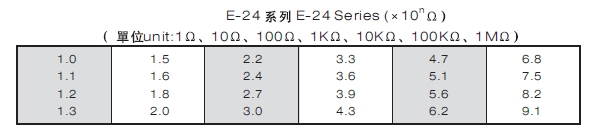
According to the table above, we can know that 472=4700Ω=4.7kΩ.
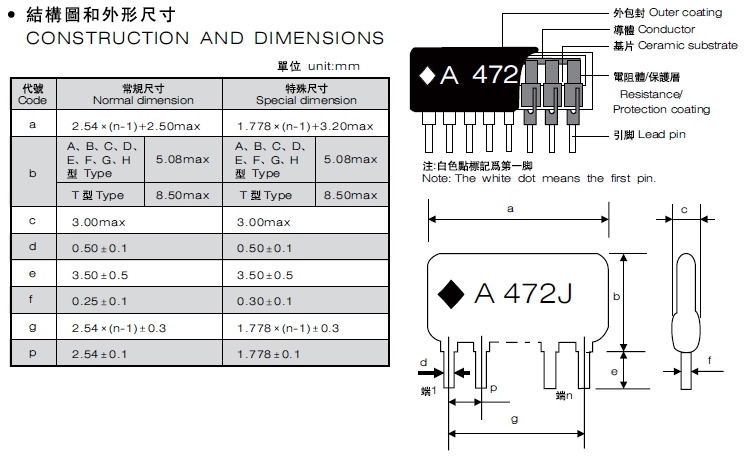
Knowing the naming rules of resistor networks, we need to understand the resistor network’s internal structure deeply. A thick film network resistor consists of the following parts: Outer coating, Conductor, Ceramic substrate, Resistance/Protection coating, and Lead pin. The construction and dimensions of the resistor network show in the figure below:
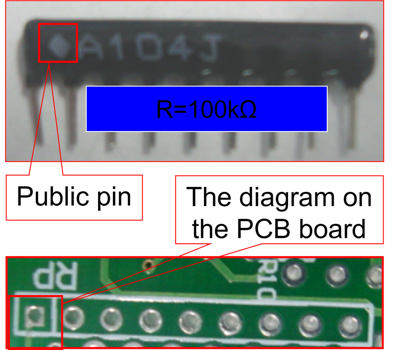
Did you notice a square mark on the far left of the dimension printing? The network resistor is composed of several resistors. One pin of these resistors must be connected as a joint pin; the rest are lead out typically. Therefore, if a block is made of N resistors, it has N +1 pins. Generally speaking, the leftmost pin is the public pin, usually marked with a white dot on the network resistor. The figure below explains the relationship between the available pin and the PCB board.
Conclusion
In summary, resistor networks are electronic components used in various electronic applications to control current flow. They can be made up of multiple resistors connected in series, parallel, or a combination of both to achieve a specific electrical function. The ratings of resistor networks include the resistance value, power rating, tolerance, and temperature coefficient. The model of a resistor network can be identified by checking the markings on the resistor network, consulting the data sheet, measuring the resistance value, or comparing the physical characteristics to standard models. It is essential to correctly identify the resistor network model to ensure proper selection and use in electronic circuits.
The network resistors from RisunSemi
RisunSemi recommends high-quality network resistors to you. Click the link below to search for the network resistors you need!