

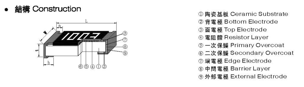
Struktur des Chipwiderstands
Der Chipwiderstand besteht aus vier Teilen: dem Substrat, der Widerstandsfilmschicht, der Elektrode und dem Schutzmedium. Der Elektrodenteil ist in die Innenelektrode (Silber-Palladium), die Übergangsschicht (Nickel) und die Außenelektroden (hauptsächlich Zinn) unterteilt -Strontium).
Das Substrat des Chip-Widerstands besteht aus einem hochreinen Aluminiumoxid-Keramikmaterial, das eine außergewöhnlich hohe mechanische Festigkeit und Isolationsfestigkeit, eine hervorragende Wärmeleitfähigkeit und eine hohe Temperaturbeständigkeit aufweist. Die Widerstandsfilmschicht besteht nach hohen Temperaturen hauptsächlich aus Glasglasurpaste auf Rutheniumoxidbasis. Das Abfeuern macht es; Die Innenschichtelektrode besteht im Allgemeinen aus Siebdruck oder ist getaucht, und die erneut gesinterte Silberschicht, die Übergangsschicht und die Außenelektrode sind genotypisch für galvanisiertes Nickel und Zinn. Die Schutzschicht ist eine bei ungewöhnlicher Temperatur gesinterte Glasur.
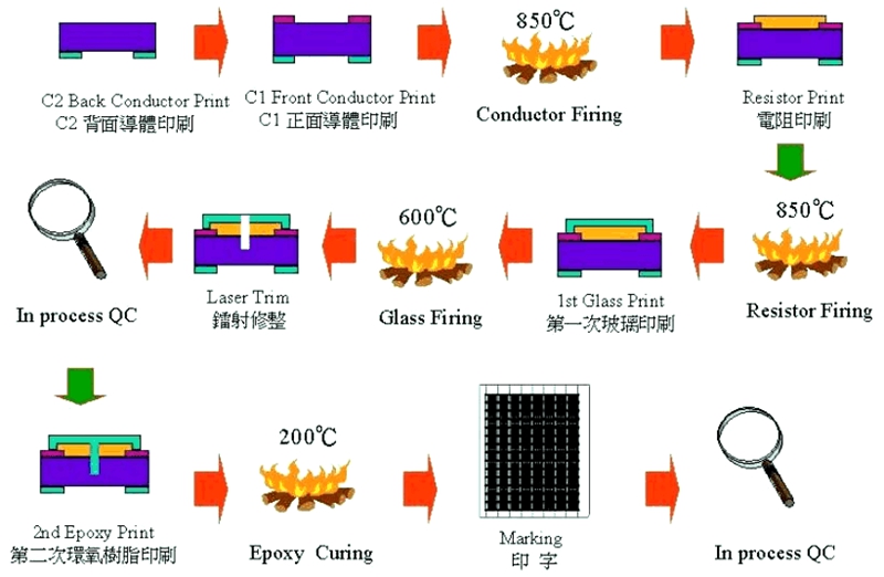
Herstellungsprozess und Prozess von Chip-Widerständen
Rückelektrodendruck → Brennen → Oberflächenelektrodendruck → Brennen → Widerstandsdruck → Brennen → Primärglasdruck → Brennen → Lasertrimmen → Sekundärglasdruck → Markierungsdruck → Brennen → Primärschneiden → Endversiegelung → Brennen → Sekundärschneiden → Galvanisieren von Elektroden → Test Sortieren → Kleben und Verpacken
Probleme bei der Anwendung von Chip-Widerständen
SMD-Widerstände werden im Allgemeinen in großem Maßstab automatisiert hergestellt und die Produktkonsistenz ist gut. Die häufigsten Probleme beim Materialeingang sind nicht viele, und die folgenden Probleme treten häufig während der Verwendung auf:
1 Elektrode fällt ab: Wenn dies nach dem Schweißen passiert, sollte die Ursache unter zwei Aspekten analysiert werden: Erstens ist die Elektrodenhaftfestigkeit des Widerstands selbst nicht gut, und zweitens brennt die Elektrode aufgrund der hohen Temperatur während des Schweißens, insbesondere während des Schweißens manuelle Schweißsituationen. Diese Situation wird durch den Lötwärmebeständigkeitstest (260℃*10S, geprüft unter einem Mikroskop) bestätigt.
2 Substratbruch: Diese Situation wird hauptsächlich dadurch verursacht, dass der Widerstand durch äußere mechanische Beanspruchung beschädigt wird. Natürlich kann thermische Belastung auch zum Bruch des Substrats führen, doch kommt dies in der Praxis selten vor.
3 Variation des Widerstandswerts: Im Allgemeinen wird der Widerstandswert stärker und fällt aus. Diese Situation wird hauptsächlich durch eine langfristige Überlastung verursacht. In Chip-Widerständen verwendete Schaltkreise weisen häufig eine relativ hohe Bauteildichte und schlechte Wärmeableitungsbedingungen auf. Wenn Sie über einen langen Zeitraum unter solch rauen Bedingungen arbeiten, sollte bei der Auswahl der Widerstände eine Leistungsreduzierung durchgeführt werden, um die Lebensdauer der Chip-Widerstände zu verlängern.
4 Oxidation der Außenelektrode: Diese Situation beeinträchtigt die Schweißwirkung des Chipwiderstands und kann leicht zu Fehlschweißungen führen. Ob die Außenelektrode oxidiert ist, kann anhand zweier Aspekte beurteilt werden. Eine besteht darin, unter einem Mikroskop zu beobachten, und die äußere Elektrode ist schwarz; Die andere besteht darin, einen Lötbarkeitstest (235 °C*3 Sekunden) durchzuführen, um das Zinn auf der Außenelektrode zu halten (erfordert eine Lotabdeckungsfläche des Anschlusses von mehr als 90 %).
Fallstudie zum Widerstandsausfall 1
Fall 1: Guangdong XXX Electronics Co., Ltd. Fall eines V9636-Hauptpanels mit Widerstandsbruch
Time: July 10, 2020
Recently in the quality control report of the production line, R407/2.2Ω resistors break on the main panel of A V9636 were found with a defect rate of 0.5% (sometimes as high as 4%). The root cause of the badness here is:
1. The V-groove between the panels of the AV9636 main panel is relatively shallow, and it isn’t easy to separate the boards. The manufacturer used too much force during the board-splitting process, breaking the resistor body
2. For the defective products brought by the engineering personnel, the relevant personnel of Gaohua confirmed that some of the semi-finished PCB boards had not been tested
Our company’s solution to the above problems is as follows:
1) Relevant personnel must inform the PCB manufacturer to change the V-groove, and IQC is responsible for confirming the effect of the change.
2) Please ask the developer to change the PCB board (AV9636-0), R408 to 2.2Ω, and R407 to a copper skin for a direct short circuit.
3) For the semi-finished PCB boards in stock (AV9636-0), after communicating with the outsourced manufacturer, we agree to return the boards that arrived before July 10, 2020, to the factory without affecting the average production of our factory Retest.
4) The outsourced manufacturer will make the corresponding sub-board tooling for the produced PCB board during production, and the outsourced manufacturer will design the tooling;
5) Personnel testing must be arranged when our production line uses the boards that arrived before July 10, 2020.
Resistor Failure Case Study 2
Case 2: Zhejiang XXX Electronic Technology Co., Ltd. VD017K game has no function case
Time: July 5, 2018
the product line produced VD017 K, and about 70% of the games on the machine had no function (sometimes no function). After analysis and testing, it was found that the decoding board R17 (6.8 kΩ /1/16W) deteriorated, resulting in low voltage. This board is a new patch, batch numbers: 2629 and 2630. Now do the following:
1. For further analysis and verification, please use another manufacturer’s 6.8kΩ / 1/16W (material number: 0090002) chip resistor 300PCS.
2. Replace R17 directly when reproducing, measure the resistance value after completion, and ask QE to verify.
3. The supply department should notify the external manufacturer to assist in the investigation of the resistor supplier, suspend the use of resistors from this manufacturer, and at the same time invite the manufacturer to come to take samples and analyze them.
4. Please ask the Type Experiment Center to test and verify all the specifications of the manufacturer’s resistors and take samples of the wrong resistors for analysis.
5. Please ask the relevant department to check the inventory of the resistors of this manufacturer and check whether there are resistors of the exact specification from other manufacturers simultaneously. If not, please immediately ask the supply department to purchase a resistor of the precise specification from other manufacturers.
After re-examination, the main reason for the failure of chip resistors is caused by poor test fixtures. There is a row of thimbles on the decoder board test frame (this row of thimbles is on the game signal output socket of the decoder board), and there is a skew phenomenon. Resistor failed.

The Chip Resistors from Risunsemi
Risunsemi recommends high-quality chip resistors to you. Click the link below to search for the chip resistors you need!